

A finished LEGO MOC might look perfect on screen while still being difficult for another builder to assemble. The difference is the instruction sequence: a useful guide reveals the right parts at the right moment, explains where they connect, and does not hide essential work behind pieces already installed. BrickLink Studio’s Instruction Maker provides the tools to build that guide, but the designer still has to decide what makes sense to the person following it.
This walkthrough covers the process from a saved digital model to a printable PDF. It also explains how to check your pages before you share them. The advice is based on Studio’s official help documentation and an independent community guide; it is not a report of a hands-on test of a particular MOC.
Start with the reader, not the export button
Before creating pages, examine your Studio model for misplaced parts, unexpected colors, disconnected elements, and awkward connections. Save a working copy. Then imagine a builder starting with a pile of loose pieces rather than a view of the completed model.
Identify a stable starting point, parts that must be attached before an area is covered, and sections best assembled away from the main build. This is particularly important for sideways connections, delicate structures, and interiors that become inaccessible once the roof or outer shell is attached.
Think of the job as three related tasks: make the model understandable, make the assembly order workable, and make the pages readable. Attractive page design cannot rescue a sequence that requires someone to dismantle earlier work.
Organize repeatable sections with submodels
In Studio, a submodel is an assembly treated as a smaller unit of the design. A wheel module, shop-window frame, removable roof, or identical row of seating may be easier to explain separately. Select the relevant parts in Building mode, choose Create into Submodel in the viewport status bar or the context menu, and give the assembly a useful name. The official help also documents the Ctrl+G shortcut.
Submodels are especially helpful for repeated structures. When you clone a submodel, its copies are linked; changing one updates the linked copies. That is convenient for truly identical assemblies, but it can be surprising if a later modification is meant to affect only one side of an asymmetric model.
Do not turn every handful of pieces into its own submodel. A good division reflects how a person would hold, assemble, and attach a component. If a small assembly needs only two straightforward steps, it may fit in a compact callout later; a larger one may deserve several full pages.
Create a build sequence in Instruction Maker
Open Instruction Maker from Studio’s toolbar or through Tool → Instruction Maker. It has two main areas: Step Editor, for creating and organizing assembly steps, and Page Design, for turning those steps into print-ready pages.
Use Step Editor to assign parts to the step in which they should be added. For a submodel, select it and use View Steps to work on its internal construction sequence; Return to Parent takes you back to the larger assembly. You can also work with steps in Building mode if that better suits your editing process.
For each step, ask: Can the reader identify the new pieces? Is their connection point visible? Can the step be performed without moving or undoing something already assembled? If not, divide the step or change the sequence.
Use automatic steps as a draft, not a promise
Studio’s Divide into Steps function can distribute selected pieces into steps automatically. According to the official documentation, you select more than one part within the current step and use the command above the parts list. Studio notes that the feature works best on simple designs with studs facing upward.
That limitation matters. A SNOT-built wall, a concealed hinge, or an assembly connected from underneath may require more thoughtful sequencing. Use the automatic result to get started, then inspect each transition. If the result is confusing, divide a smaller selection or create steps manually.
Studio documents a useful manual approach sometimes called peeling the onion: select accessible outside pieces, move them to a new step after the current one, and keep working inward until the remaining build forms a sensible starting step. The guiding rule is to keep the model connected rather than producing unexplained floating pieces.
Editorial rule of thumb: the ideal number of pieces per step depends on the connection, not on a fixed quota. Three easily aligned plates can belong together; a single hard-to-see clip might deserve an isolated view.
Design pages that explain the movement
Once the sequence works, switch to Page Design. Here Studio offers page layouts, step numbers, parts lists, highlights for newly added elements, camera angles, and page-level styling.
- Keep the viewing angle consistent. Change it when needed to reveal a hidden connection, not simply to make each page look different.
- Show new parts clearly. Review the per-step parts list and use New Parts Highlight if it improves contrast.
- Choose space over density. Group easy steps on a page; give a delicate alignment or concealed connection room to breathe.
- Mark orientation changes. A flip indication helps readers recognize when the model has been turned.
- Check smaller screens. Fine details that look clear on a large monitor may be difficult to distinguish in a PDF viewed on a phone.
Use a callout for a short subassembly that readers can construct alongside the main step. In Page Design, select a step within the submodel and choose Convert to Callout. The small instruction window appears with the step where the submodel is needed. For a complicated subassembly, regular step pages are usually easier to follow. The purpose of a callout is to clarify timing and placement, not to save pages at any cost.
A4 or US Letter? Plan for your audience
Open Page Setup to choose page size, orientation, and margins. BrickLink’s documentation recommends using a common local paper size for printable PDFs: US Letter in the United States and A4 in Europe. A digital-only guide may be less sensitive to paper size, but clear margins and legible images still matter.
If you expect both North American and European builders to print the file, check how the chosen layout behaves on each paper size. Avoid placing step numbers, part labels, or assembly arrows close to the page edge. If printing is a major part of the project’s intended use, consider preparing separate layouts and exports rather than assuming that every printer’s automatic scaling will preserve readability.
Consider an uncluttered cover with the MOC name, an accurate picture or render of the finished design, the creator’s credit, and a brief description of what the file includes. Do not invent a product box or imply that a fan-made guide is an official LEGO instruction booklet.
Add a complete parts inventory
Step-level parts lists tell the builder what to pick up for a particular step. A Bill of Materials (BOM) provides the inventory for the entire design. It is useful when someone wants to gather pieces before starting or check whether the model can be built from their existing collection.
In Page Design, add a page toward the end of the instructions, then select + Insert → Bill of Materials. Studio can create additional pages if the inventory does not fit. The BOM settings include display options such as BrickLink part IDs with color codes or names, LEGO Element IDs, and quantities. A BrickLink part ID and a color-specific Element ID are not interchangeable identifiers, so choose labels that match the intended reader’s needs.
Review the inventory instead of trusting the exported appearance alone. Look for stray pieces, incorrect colors, or last-minute edits that should have changed the intended inventory. For a large MOC, check how the list flows onto additional pages and whether the parts remain recognizable.
Export a PDF and check the actual file
When the pages are ready, click the green Export button at the top right of Instruction Maker’s page-design area. You can export all pages, selected page numbers, or a range. The official exporter supports PDF as one printable document and PNG as separate images for each page. It also provides an image-size or zoom setting and a file-location choice.
PDF is the most practical default for a complete guide. PNG can be useful for reviewing individual page images or showing a sample of the instructions. Increasing the export zoom can improve image detail while making output files larger and export slower.
Do a final check outside the editor: open the exported PDF, view it at a realistic phone-screen size, scan through the complete page order, and preview how it would print. Pay attention to clipped arrows, tiny quantities, indistinguishable colors, and sudden changes of camera angle. Successful export confirms that a file was generated; it does not establish that someone can build the model from it.
Worked planning example: a small street-food cart MOC
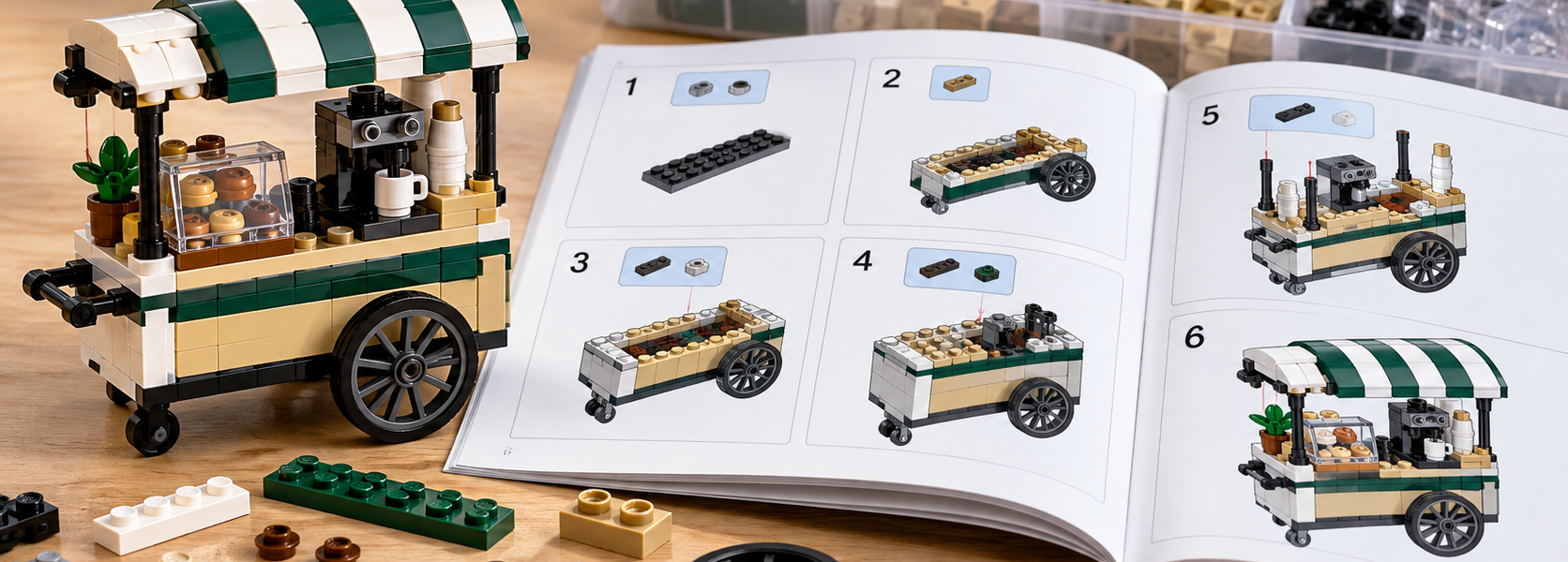
Consider a hypothetical street-food cart with a base, two repeated wheel assemblies, a counter, side panels, and a detachable canopy. This is an illustrative sequence, not a physically tested model.
- Base: begin with the stable chassis so the reader has an obvious reference point.
- Wheel units: give a repeated assembly its own submodel, then show clearly where the copies attach.
- Counter and interior: install hard-to-reach pieces before surrounding walls restrict access.
- Side panels: reveal their attachment points from a consistent viewing angle.
- Canopy: build it separately, using a callout only if its internal construction is simple enough to fit, then attach it last.
A weak instruction might show the cart nearly complete and ask the reader to add several hidden fittings at once. A stronger one separates those actions, indicates which parts are new, and makes the connection locations visible. This is the core difference between a record of how a model looks and a guide to how it can be built.
Before sharing your instructions: a practical checklist
- Does the first step establish a stable foundation?
- Does every step make the new parts and their attachment points identifiable?
- Are the connections physically reachable in the specified order?
- Do submodels appear before they are needed, with repeated modules handled consistently?
- Are difficult rotations, offsets, or attachment directions explained rather than implied?
- Are parts lists, page numbers, and model views readable on a phone and on paper?
- Does the final BOM reflect the intended part selection and colors?
- Have you opened and reviewed the exported PDF instead of checking only the Studio preview?
- Are the project’s author and any third-party contributions accurately credited? Are the permissions for any reused designs or images understood?
- If the model has not been physically test-built using the instructions, is that limitation made clear?
For public distribution, keep the editable Studio project backed up even if you share only the PDF. It makes future corrections much easier. Explain what recipients will receive, such as the PDF alone or the PDF plus an optional editable project file. Sharing a copy of your own design and using someone else’s design or artwork are different situations: check the applicable permissions rather than assuming that all fan-made content is free to redistribute.
The goal is a buildable guide, not just a polished PDF
BrickLink Studio can automate parts of the workflow, but clarity comes from the designer’s decisions. Organize submodels around realistic assembly tasks, use automatic steps selectively, make connections visible, and check the final export in the formats your readers will actually use. If possible, have someone build the MOC from the instructions without extra guidance. That is the strongest way to reveal missing or misleading steps.
Sources and further reading
- BrickLink Studio Help Center — Introduction to Instruction Maker
- BrickLink Studio Help Center — Submodel
- BrickLink Studio Help Center — Automatic Instructions / Divide into Steps
- BrickLink Studio Help Center — Page Design Interfaces and Elements
- BrickLink Studio Help Center — Callout vs. Step View
- BrickLink Studio Help Center — Page Setup
- BrickLink Studio Help Center — Bill of Materials
- BrickLink Studio Help Center — Exporting Instructions
- Open L-Gauge — Making High Quality Building Instructions in BrickLink Studio