
LEGO MILS Explained: How to Build Modular Bases and When They’re Worth It

Imagine arriving at a LEGO exhibition with a carefully detailed railway scene. The builder next to you has brought an equally impressive station, but the ground sits at a different height, the tracks do not meet and neither landscape has an obvious way to connect to the other. Both models look great on their own. Together, they suddenly become a puzzle.
MILS—Modular Integrated Landscaping System—was created to make collaborative layouts easier. Its appeal is not a special type of scenery or a particular color of baseplate. It is the idea that builders can agree on a few shared connection rules while keeping their creative freedom everywhere else. Drawing on the original HispaBrick documentation, club-building examples and railway builder Michael Gale’s practical guide, this article explains how to approach MILS without committing an entire collection to raised baseplates.
What MILS standardizes—and what it deliberately leaves alone
The system emerged from the HispaBrick Magazine community’s plans for large displays assembled by different builders. Antonio Bellón documented the approach for HispaBrick, with the original rules and explanations also available on the MILS reference website. It is a fan-developed building standard, not an official LEGO building system.
The key distinction is often missed: MILS does not require every square inch of a display to be built as a MILS module. The rules matter primarily where sections must meet. If you and your LEGO User Group (LUG) agree on compatible edges, heights and connection points, the internal construction of a mountain, castle courtyard or train yard can remain your own decision.
For clubs, this means one member can contribute a forest while another supplies roads or water. For solo builders, it creates a repeatable way to rearrange a layout without permanently attaching everything to a single tabletop. Neither outcome requires starting with dozens of identical squares.
Inside a basic 32 × 32 MILS base
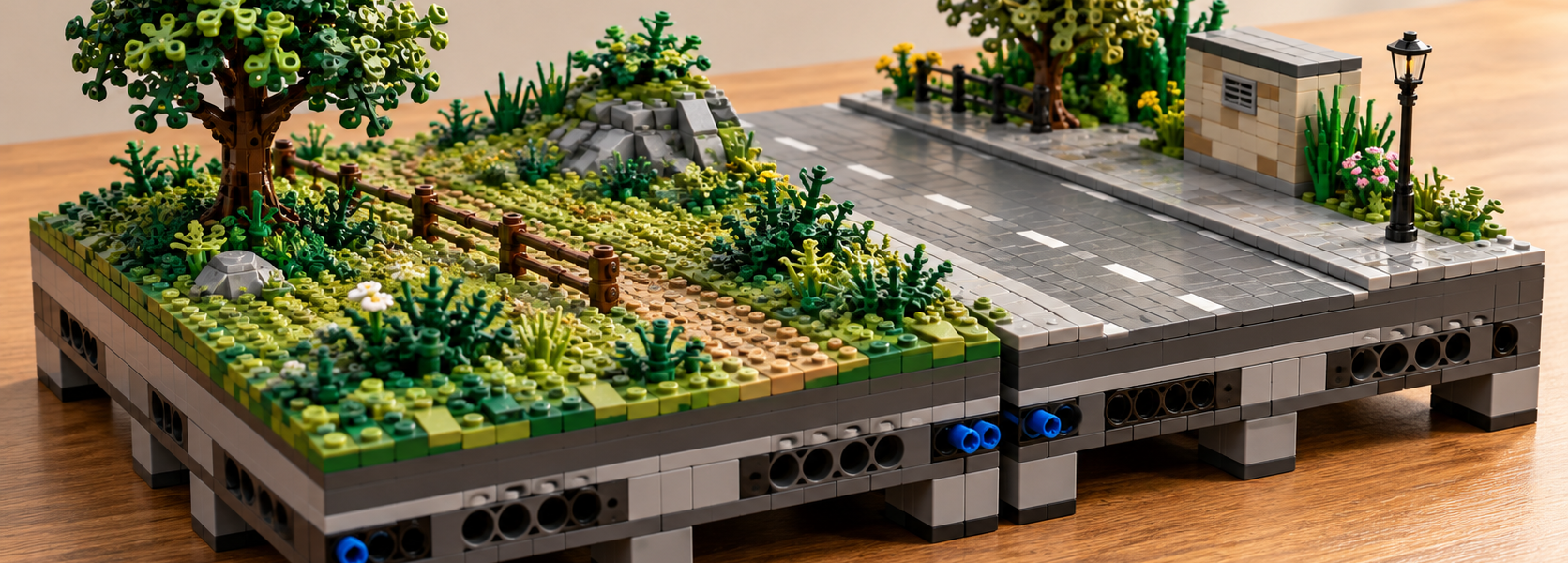
The original system uses a 32 × 32-stud Basic Terrain Unit (BTU) as its primary footprint. A conventional flat module starts with one 32 × 32 baseplate, or an equivalent combination of smaller baseplates covering the same area. It then raises the nominal ground surface by four plate heights above that baseplate: commonly a one-brick-high structural layer topped by a regular plate. Because a brick is three plates tall, the dimensions add up without requiring a stack of four bricks.
The following features matter most:
- Base: a thin LEGO baseplate, not a regular thick building plate. That distinction matters when checking the final height.
- Edges: a brick-high framework with 1 × 4 Technic bricks beside the corners. Their holes accept pins that connect adjoining modules.
- Corners: a 2 × 2-stud location at each corner can identify a builder or a group with a distinctive color. The original specification recommends identifiers but does not make a particular marker compulsory.
- Internal supports: bricks placed where the upper plates need support. There is no single prescribed pattern that works for every plate size.
- Top surface: regular plates covering the supports, ready for grass, paving, ballast or other scenery.
For a level field, the nominal top is one baseplate plus four plate heights. This creates space beneath the visible ground and helps the resulting module resist bending when properly supported. It also gives builders an opportunity to shape a ditch or watercourse below the surrounding land. Michael Gale explains these benefits in his BrickNerd guide to modular train layouts.
Build a first MILS module without buying an entire new parts collection
Rather than converting a whole town immediately, begin with a plain square of terrain. The following is a source-based building outline, not a physically tested model or a verified parts inventory. Support positions and the exact pieces used will depend on the plates available to you.
- Set out the footprint. Start with a 32 × 32 baseplate. Choose the color you already own; much of it will be hidden.
- Reserve the corners. Keep the 2 × 2-stud corner identification positions in mind and decide whether you need color markers for a shared display.
- Position the connectors. Add the 1 × 4 Technic bricks alongside the corners on the relevant sides, with their holes facing outward. Their positions need to match those on the neighboring modules.
- Build the frame and supports. Continue the one-brick-high layer around the edges and place supports beneath the intended top plates. Larger plates should not be left to flex under pressure.
- Close the top. Add ordinary plates to reach the correct ground level. Use inexpensive or mismatched colors for hidden structural bricks if they are available and suitable.
- Test an actual join. Bring a second compatible module—or a correctly built test edge—against the first, insert Technic pins and check that the top surfaces sit level without forced connections.
- Add scenery last. A small patch of grass, paving or rocks is enough to see whether the module remains convenient to handle and store.
Cactus Brick’s landscaping documentation, written by Corey Gehman, illustrates this type of construction with a 32 × 32 grass module. The group used 6 × 8 plates for the upper surface and deliberately added extra internal support where a plate would otherwise bend. Its example also shows optional Technic bricks near the middle of an edge—useful in that build, but not a universal requirement of MILS.
Before copying a parts list from any guide, ask whether you need the same color, the same plate sizes or the same number of supports. The underlying geometry and compatible edge connections matter more than an identical set of hidden filler bricks.
BTM, CTM and TTM: three labels with different jobs
The original MILS descriptions distinguish the main types of module because an open grass field is not the same design problem as a river or a railway.
- BTM — Basic Terrain Module: a 32 × 32 unit whose four sides can connect consistently with neighboring terrain. A self-contained patch of meadow or desert is a typical example.
- CTM — Compatible Terrain Module: also based on a 32 × 32 unit, but its features need specific neighboring connections. A road, river, seashore or a hill continuing into another module cannot simply be rotated anywhere in a layout.
- TTM — Transition Terrain Module: a connecting piece, potentially of a different footprint, used to join a MILS area to scenery or structures built outside the MILS rules.
The full descriptions appear in the original MILS specification. In practice, builders also use intermediate sizes such as 16 × 32 studs, particularly for train layouts. These can be compatible with the wider arrangement when their joins are planned properly; they should not be mistaken for the original 32 × 32 BTU definition. A club may adopt additional variations, so always check the event’s agreed standard.
The exhibition problem: matching scenery is only half the job
Suppose three members of a LUG plan a public display. One is bringing a forest, one a road and one a railway. A common MILS base height helps, but it does not automatically make the scenery line up. The team still needs to agree on what crosses each boundary.
Before building, share a simple map showing the intended position of each module. For every shared edge, record the terrain level, where the road or track meets it, and which side has the mating Technic connections. For a water feature, agree on where the channel continues and the level of the water surface. Keep the same colors at the seam if a smooth landscape transition is important.
The original rules even describe reference connections for different features: a path may cross the center of a compatible edge at four studs wide, a broader track at eight studs, a paved road at sixteen, and a river at an eight-stud opening. These are specific interface conventions for relevant module types, not restrictions on the whole interior of every builder’s landscape. For an independently designed city or club layout, compatibility has to be an agreement, not an assumption.
Cactus Brick offers a practical example of why the system exists: its members documented sections built by different people that could still form a coherent landscape, despite variations in the details. That collaboration is more revealing than a photograph of a single perfect baseplate.
Why railway builders find MILS particularly useful
Train layouts amplify the usual problems of exhibition planning. Sections must carry track at a consistent level; points, crossings and curves need reliable alignment; and large scenes may need to fit a different table footprint at each venue. Michael Gale describes moving away from a large fixed arrangement toward portable MILS-supported railway sections that could be combined in different configurations.
His examples include intermediate straight-track modules, double-track modules, curve sections, crossings and raised terrain with drainage details. Some use a sparse support structure under the track instead of covering the entire module with expensive top plates. The raised base can also provide a route for cables used by lights or accessories; a center arch-brick pass-through is a useful practice, but not a compulsory feature of the original standard.
Remember that MILS compatibility alone does not guarantee track compatibility. The rails must still meet at the correct location and height, with curves, switches and any chosen ballasting approach accounted for. L-Gauge’s reference instruction sheets are useful for studying ballasted track components and baseplate substrates, while Gale’s article shows how track supports can be incorporated into MILS arrangements. Not every L-Gauge reference sheet describes a full MILS base, so use each document for its stated purpose.
Transition sections are particularly valuable when an existing railway needs to meet a raised MILS landscape. Instead of rebuilding every piece of old track, a planned connection between the two ground levels may be more practical.
When raised MILS bases earn their cost—and when they do not
The advantages are easy to understand: a well-supported raised base can be more rigid than a thin baseplate, provides room for terrain shaping, and is convenient when an exhibition has to be packed, transported and assembled repeatedly. Compatible modules can be rearranged, combined with contributions from other builders or grouped differently to fit the space available at a new venue.
But the extra structure is not free. A conventional baseplate-based scene uses fewer hidden bricks and plates. MILS adds a framework, top plates, supports and specific edge connectors. It also makes the finished scene thicker and potentially heavier. There is no reliable universal price per 32 × 32 module: the cost depends on your inventory, local sourcing, plate sizes and the design you choose. We have not constructed or priced a verified bill of materials for this guide.
MILS is usually worth considering when you exhibit with a group, frequently transport a large layout, want consistent reusable terrain modules, or expect to rearrange trains, roads and landscape for different spaces.
It may not be worth the conversion for a single shelf display that rarely moves, for a large completed city whose roads and buildings would need extensive reworking, or when your limited parts budget would be better spent on the visible model. Raised modules are a building choice, not a quality badge.
A sensible migration plan for an existing LEGO city or train layout
Converting every baseplate at once is the most expensive way to discover that MILS does not suit your project. A safer approach is to test one representative section before committing.
- Identify your real constraint. Is the problem transport, modular expansion, joining club displays or uneven terrain? If none applies, you may not need MILS.
- Choose one pilot module. Build a simple section that can be compared with existing scenery without dismantling the whole layout.
- Check the seams. Measure ground and track levels, road alignment, pin locations and any feature that continues into a neighboring section.
- Count the hidden parts. Note which elements came from spare stock and which would require additional purchases. Only then estimate how much a full conversion might consume.
- Plan a transition if required. An older baseplate city, large display or legacy train section does not have to be destroyed merely to join a newer raised area.
- Trial the practical workflow. If the aim is exhibition use, rehearse carrying, connecting and separating the modules safely before scaling up.
For a LUG, write down the agreed edge profiles and share them before anyone starts building. Common assumptions lead to incompatible modules more often than a lack of sophisticated LEGO pieces.
A shared foundation, not a creative restriction
The most interesting part of MILS is the freedom it preserves. The system gives collaborators a dependable meeting point without requiring identical scenery, identical internal supports or even a completely MILS-built exhibition. A collector with one small landscape can use the idea selectively; a railway group can make it a central part of how it plans and transports a display.
Start with a single compatible section and decide whether its benefits outweigh the parts it consumes. If it solves a problem you already have, MILS can be a powerful foundation. If it does not, there is nothing wrong with a good old baseplate.
Sources and further reading
- HispaBrick community — Original MILS specification: purpose, basic units, module categories, edge conventions and transition modules.
- Michael Gale, BrickNerd — How To Modularize Your LEGO Train Layout with MILS: practical railway adaptations, benefits, costs, transport and wiring.
- Corey Gehman / Cactus Brick — Landscaping Standard: club collaboration and illustrated construction of basic terrain and river sections.
- L-Gauge — Reference Instructions: track ballasting and compatible substrate examples; not all listed sheets describe complete MILS modules.